
IA Lab #3: Planning, AI & Soldering
- Corrina Crazie Espinosa
- Feb 1
- 10 min read

Part 1: Planning the Layout & Permanent Wiring
Before you solder a single joint or commit anything permanently, you need a plan. Interactive light artworks aren’t just visual objects—they’re systems. How you power, route, expose, and secure those systems directly affects how the work functions, how long it survives, and what it communicates.
This phase is about thinking like an artist and a builder.
1. Choosing the Right Power Supply
Power is not just a number on a label. It’s behavior over time.
When selecting a power source, consider:
Voltage requirements of all components
Current draw (amps) under full load
Headroom (never spec power at the exact maximum)
Duration of use (short demo vs. hours-long exhibition)
Heat generated by sustained power draw
An underpowered system will flicker, reset, or fail unpredictably. An overworked power supply can overheat or die early. Think of your artwork as having a metabolism—it needs consistent, reliable energy to stay alive.
Power, Voltage, and Why “It Turns On” Isn’t Enough
Different components speak different electrical “languages.”
For example:
Microcontrollers (like Arduino) typically operate around 5V (sometimes up to ~9V through regulated input)
LED strips often require 12V
Motors may need higher voltage and significantly more current than logic circuits
This means a system can appear simple on the surface—but underneath, it may be balancing multiple electrical needs at once.
Voltage determines what a component can accept.Current, measured in amps (A), determines how much work it can actually do.
Current (Amps): The Thing That Bites You Later
Voltage gets the attention, but current is what quietly causes failure.
As you add:
More LEDs
Brighter LEDs
Motors, servos, or relays
Your system’s current demand (in amps) increases—sometimes dramatically.
When a power supply can’t deliver enough current, you’ll see symptoms like:
LEDs dimming or flickering
Microcontrollers resetting randomly
Motors stalling or behaving unpredictably
This doesn’t mean your code is wrong. It often means your system is starving for current.
A good rule of thumb:
Your power supply should never be working at its maximum rated current.
Always leave headroom.
How Do You Know How Much Current Something Needs?
You don’t guess—you look it up.
Current requirements are typically found in:
Datasheets
Product listings
Manufacturer documentation
Silkscreen labels on components
Reputable tutorials or wiring guides
Examples:
LED strips are often rated in amps per meter
Motors list stall current and running current
Microcontrollers list operating current and recommended supply limits
Part of your job as an artist working with electronics is learning how to read these specs and translate them into design decisions.
Do I Really Need Two Power Supplies?
Not necessarily.
A Hacker approach!
In a time pinch, use an extension cord or a small power strip inside of your object if space permits for a fast and easy solution.
Smarter more advanced Approach: One Power Source + Voltage Regulator
Instead of multiple wall adapters, and if you don't have room for a power strip or extension cord-- you can use:
One main power supply (commonly 12V)
Voltage regulators or DC–DC buck converters to step voltage down where needed
Example:
12V supply → LED strips
Same 12V supply → buck converter → stable 5V → Arduino & sensors
This approach:
Reduces clutter
Simplifies grounding
Improves reliability
Makes the system feel intentional rather than improvised
The key requirement: All components must share a common ground.
Separate Power Behavior, Not Power Sources
Even with one supply, think in terms of power domains:
Logic power (microcontrollers, sensors)
Load power (LEDs, motors)
They can come from the same source, but they should be routed thoughtfully. Motors and high-current LEDs create electrical noise; microcontrollers are sensitive to it.
Good layout prevents bad behavior.
The Big Picture
Power planning isn’t about memorizing numbers. It’s about asking better questions:
What voltage does each component require?
How much current (in amps) does the system draw at peak?
What happens when everything turns on at once?
Where does voltage regulation simplify the system?
Is this designed for a quick demo—or for hours of operation?
When power is designed well, everything downstream behaves better.
And when it’s not… the artwork will tell you.
2. Where Does the Hardware Live?
Decide early where all electronic components will be housed:
Microcontrollers
Power supplies
Drivers, relays, or regulators
Sensors and connectors
Ask yourself:
Is everything enclosed, partially visible, or fully exposed?
Is the housing structural, sculptural, or purely functional?
Can the enclosure breathe, or does it trap heat?
Hardware placement is not neutral—it affects maintenance, safety, and meaning.
3. Planning Wire Paths (Before They Exist)
Wires should never be an afterthought.
Plan:
How wires travel from power → control → output
Where wires are bundled vs separated
How long wire runs need to be
Where wires cross moving or interactive areas
Longer runs, messy routing, or tangled signal and power lines can introduce instability. Clean layout isn’t about aesthetics alone—it’s about reliability.
4. Exposed vs Hidden Wiring (and What It Says)
Visibility is a conceptual choice.
Hidden wiring can suggest polish, illusion, or seamless magic
Exposed wiring can communicate transparency, vulnerability, labor, or system-ness
Neither is “better.” What matters is intentionality. Ask: What does the viewer learn by seeing (or not seeing) the system that powers this work?
5. Strain Relief & Physical Stress
Interactive art invites touch, movement, vibration, and accidents.
Plan for:
Where wires might be tugged or flexed
Openings that are repeatedly accessed
Movement near solder joints or connectors
Use strain relief (zip ties, clamps, grommets, hot glue) where needed. A perfectly wired circuit can still fail if the physical forces acting on it are ignored.
6. Modularity, Access, and Maintenance
Assume your work will need attention later.
Ask:
Can parts be replaced without destroying the piece?
Can you access components once it’s assembled?
What happens if one element fails?
Modular thinking doesn’t mean lack of commitment—it means care for the future of the work (and your sanity during install).
7. Safety & Responsibility
If your work is interactive or public-facing:
Avoid exposed live connections
Watch for sharp leads, hot components, pinch points
Consider how the piece behaves if left on for hours
Careful construction is a form of ethical practice.
8. Document Before You Seal It
Once the work is closed up, the system disappears.
Document:
Wiring diagrams
Photos of internal layouts
Notes on power and connections
Think of documentation as collaboration with future you (or anyone else who has to touch this piece).
9. Permanence Is a Choice
Finally, decide what kind of object this is:
Sealed and permanent?
Repairable and modular?
Fragile or intentionally temporary?
These decisions should align with the concept of the work—not just convenience.
Part 2: Using AI to Debug Code & Hardware (Without Outsourcing Thinking)
Part 2: Using AI to Debug Code & Hardware
(Without Outsourcing Thinking)
AI can be an extremely powerful studio tool when working with interactive systems—but only if it’s used intentionally. In this lab, AI is not here to replace your thinking. It’s here to help you clarify, troubleshoot, and learn.
If you use AI to skip understanding, that gap will surface the moment your project behaves unexpectedly—which it will.
1. Think First, Prompt Second
Before you ask AI anything, pause and do the human work.
Ask yourself:
What should the system be doing?
What is it doing instead?
When did it last work correctly?
What changed since then?
AI gives better answers when you give it context, not confusion.
2. Ask Precise Questions (Vagueness Gets Vague Answers)
AI is only as good as the question you ask.
❌ “My Arduino doesn’t work.”✅ “My Arduino resets when a motor turns on. I’m using a 12V supply with a buck converter for 5V logic. Grounds are shared. What might cause this?”
Strong prompts include:
The exact hardware you’re using
How things are wired
What behavior you expect
What behavior you’re observing
The smallest code snippet that shows the issue
This is not busywork—this is how you learn to debug like a professional.
3. Debug in Layers, Not All at Once
AI works best when you isolate the problem.
Break debugging into layers:
Power → voltage, current, grounding
Connections → wiring, pin numbers, continuity
Logic → code flow, conditionals, loops
Timing → delays, blocking functions, update rates
Ask AI about one layer at a time. This prevents chaos and builds real understanding.
4. Ask AI to Explain, Not Just Fix
One of the most valuable uses of AI is explanation.
Instead of:
“Fix this code”
Try:
“Explain what this function is doing line by line.”
“Why does this cause blocking behavior?”
“What assumptions does this code make about timing or state?”
“Why might this fail when more LEDs are added?”
If you can’t explain the solution afterward, you didn’t finish debugging—you just borrowed an answer.
5. Demand Sources and Double-Check Them
AI can be wrong. Confidently wrong.
Good habits:
Ask: “Where does this information come from?”
Request datasheets, documentation, or official examples
Cross-check pinouts, voltages, and current ratings yourself
Learning to verify information is part of being a responsible technologist and artist.
6. Use AI to Sanity-Check Hardware Decisions
AI is especially useful for:
Verifying wiring logic
Checking voltage compatibility
Estimating current draw
Catching common mistakes
But remember:
AI cannot see your physical build.
Sometimes you can send it an image, but sometimes your circuit is a complicated mess of wires, and an image can't be clear enough to make sense out of.
AI doesn’t know if:
A wire is loose
A solder joint is cold
Polarity is reversed
A component is overheating
Reality always wins.
7. Modify What AI Gives You
Never copy-paste without understanding.
Good signs you’re using AI well:
You tweak values
You rename variables
You simplify or restructure code
You test changes incrementally
Your goal is not obedience—it’s comprehension.
8. Ask AI to Check Your Reasoning
Some of the best prompts sound like this:
“Does this logic make sense?”
“What edge cases am I missing?”
“If this fails, where would you look first?”
“What’s the simplest version of this system?”
This turns AI into a thinking mirror, not a crutch.
9. Know When to Stop Asking AI
If you’re stuck in a loop of prompting without testing, pause.
At some point, the next step is:
Measuring voltage
Unplugging components
Simplifying the system
Rebuilding one part cleanly
AI is powerful—but hands-on testing completes the loop.
10. AI as Studio Literacy
Using AI well is not about speed—it’s about agency.
The goal is:
Not to avoid AI
Not to rely on it blindly
But to use it as a collaborator that sharpens your thinking
You are still responsible for the system you build.
If AI helps you understand why something works or fails, it’s doing its job.
Final Rule of Thumb
If AI gives you an answer, you should be able to:
Explain it
Test it
Defend it
If you can’t do all three, you’re not done yet.
Part 3: Soldering Basics
(Simple Theory + Common-Sense Technique)
Soldering is basically making a reliable metal connection—electrically solid and mechanically strong. The goal isn’t a big blob of solder. The goal is a clean joint where solder has flowed smoothly between the parts.
1. Flux, Rosin Core, and the “Do I Need Flux?” Question
Most solder you’ll use in class is rosin-core, which means it already contains flux inside it. Flux helps solder stick by cleaning oxidation while you heat the joint.
For most beginner joints, rosin-core solder is enough.
Extra flux can still be helpful for:
Old/dirty pads
Stubborn wires
Desoldering or rework
Very small pads where you want fast, clean flow
So: you usually don’t need separate flux to get started, but flux is still a legit tool (not a “cheat”).
2. Lead-Free Solder: Safer, Not “Safe”
Most modern classrooms use lead-free solder, which is much less toxic than leaded solder (good). But a few important truths:
Lead-free solder typically needs a bit more heat than leaded.
The fumes aren’t “lead fumes,” but you still don’t want to breathe them.
Wash hands after handling solder and components (always).
We’ll use ventilation and common sense: don’t inhale the smoke, don’t touch your face, wash up after.
3. The Golden Law: Solder Flows Toward Heat
This is the key concept.
Solder moves toward the hottest metal. So if you heat the right place, solder will follow.
Use this to your advantage:
Heat the joint (the pad + the component lead/wire), not the solder
Feed solder into the joint once it’s hot
If the solder is melting but not flowing nicely, the joint isn’t hot enough (or it’s dirty)
A Step-by-Step, Common-Sense Soldering Method
Step 0: Set Yourself Up
Stable surface, good light
Sponge or brass wool to clean the tip
Helping hands / vise if needed (movement ruins joints)
Step 1: Prep the Parts
Strip wire cleanly (not halfway shredded)
Twist stranded wire so it behaves
If possible: tin the wire (see below)
Step 2: Clean + Tin the Tip
Heat the iron
Wipe tip clean
Add a tiny bit of solder to the tip (this helps heat transfer)
A clean, tinned tip is the difference between “easy” and “mysteriously impossible.”
Step 3: Heat the Joint (Pad + Lead/Wire Together)
Touch the iron tip so it contacts both pieces of metal
Hold steady for a moment
Step 4: Feed Solder to the Joint (Not to the Tip)
Bring solder to the joint area (where metal meets metal)
Let the joint melt the solder
You’ll see it “wick” and flow when it’s right
Step 5: Remove Solder, Then Remove Heat
Order matters:
stop feeding solder
pull solder away
remove the iron
Step 6: Don’t Move It
Hold still for a second while it cools. Movement creates a weak, grainy joint.
Tinning (Optional, but Makes Everything Easier)
Tinning = pre-coating a wire or pad with a small amount of solder.
Why it helps:
Faster final soldering
Cleaner joints
Less time holding heat on components
How:
Heat wire → touch solder → let it soak through strands → stop
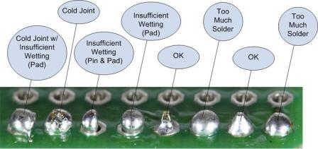
What a Good Solder Joint Looks Like
✅ Good joint:
Smooth, shiny/satin (lead-free can look slightly less shiny—still fine)
Looks like a small volcano cone
Clearly bonded to pad and lead/wire
❌ Common problems:
Blob (too much solder, not enough control)
Cold joint (dull/grainy, usually not heated enough or moved while cooling)
Bridge (solder accidentally connecting two pads)
Lifted pad (too much heat too long—gentle, quick work prevents this)

Troubleshooting in One Breath
If solder won’t stick: clean tip, heat joint longer, try a tiny bit more solder
If it beads up: joint not hot enough or surface is dirty
If it looks dull and chunky: cold joint → reheat briefly and let it flow
If things get messy: stop, clean tip, reset (don’t fight chaos)
Insulating & Protecting Soldered Connections
Once a joint is soldered, it still needs protection. Bare metal can touch other conductors, vibrate loose, or short your system—especially in interactive or enclosed works.
Insulation is part of finishing, not an afterthought.
Heat Shrink Tubing (Preferred)
Heat shrink is the cleanest and most reliable option.
Slide the tube on before soldering
Solder the joint
Slide the tube over the exposed metal
Apply heat (heat gun or carefully with the side of the iron)
Why it’s great:
Clean, professional finish
Strong insulation
Doesn’t unravel or degrade easily
If you plan ahead, this should be your first choice.
Electrical Tape (Acceptable, but Temporary)
Electrical tape works, but it has limits.
Can loosen over time
Adhesive can get gummy with heat
Not ideal for long-term or moving parts
It’s fine for:
Prototyping
Quick fixes
Temporary protection
But don’t rely on it for permanent installs unless you have no other option.
Hot Glue (Context-Dependent)
Hot glue can be surprisingly useful—but it’s not electrical insulation by itself.
Best uses:
Strain relief (preventing wires from flexing at joints)
Securing connections so they don’t move
Reinforcing soldered areas after insulation
Limitations:
Can soften with heat
Not ideal as the only barrier between conductors
Hot glue works best in combination with heat shrink or proper insulation.

The Big Idea
Your solder joint should be:
Electrically sound
Mechanically stable
Properly insulated
If two exposed conductors could touch at some point, assume they will.
Good insulation prevents:
Shorts
Intermittent failures
Mystery bugs that waste your time later
This is part of building work that lasts.
Comments